📋 Overview
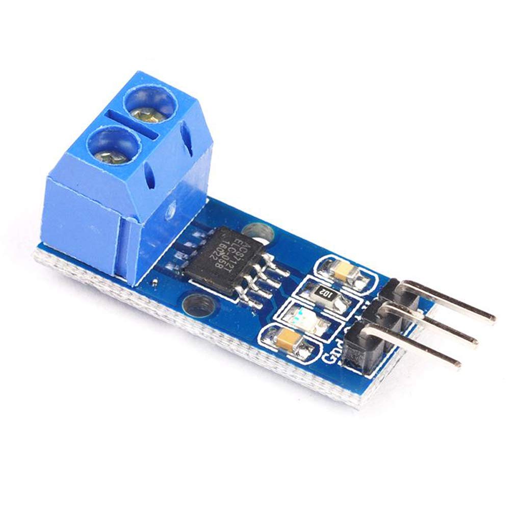
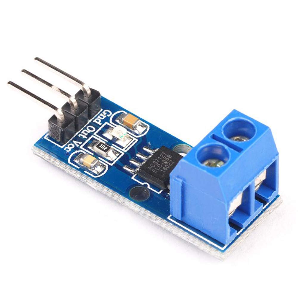
The ACS712 Hall Effect Current Sensor Module lets you measure both AC and DC current using an analog voltage output that's easy to read with any Arduino, ESP32, or other microcontroller. Built around the Allegro ACS712 Hall-effect IC, this module provides galvanic isolation between the measured circuit and your control electronics, so you get accurate current readings without physically breaking into sensitive low-voltage wiring. Choose the range that matches your project: 5A for low-power electronics, 20A for general-purpose motor and power supply monitoring, or 30A for higher-current battery, solar, and inverter applications.
⭐ Key Features
- Available in 5A, 20A, or 30A Ranges — select the option that matches your application below
- Hall-Effect Current Sensing — no series resistor, minimal insertion loss
- Electrical Isolation — 2.1kV RMS isolation between the current path and the signal/output side
- Analog Voltage Output — proportional to current, centered at 2.5V with no current flowing
- Measures AC or DC Current — suitable for both types of loads
- Fast Response — 80kHz bandwidth, 5µs output rise time
- Low Internal Resistance — 1.2mΩ conductor path minimizes power loss and heating
- Simple 3-Pin Header — direct connection to any 5V-logic microcontroller
- Screw Terminal Current Path — solder-free connection for the current-carrying wires
📊 Specifications
| Sensor IC | Allegro ACS712 |
| Sensing Method | Hall-effect, linear |
| Current Type | AC or DC |
| Supply Voltage | 5V DC |
| Zero-Current Output Voltage | 2.5V (Vcc / 2) |
| Output Signal | Analog voltage, proportional to current |
| Bandwidth | 80 kHz |
| Output Rise Time | 5 µs |
| Total Output Error | ±1.5% at 25°C |
| Internal Conductor Resistance | 1.2 mΩ |
| Isolation Voltage | 2.1kV RMS |
| Operating Temperature | -40°C to +85°C |
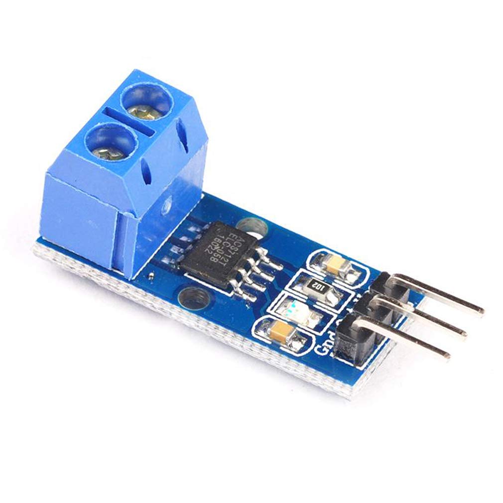
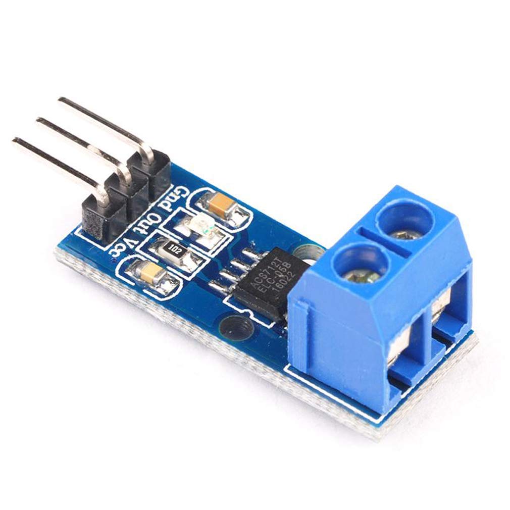
| Connector Type | 3-pin breakout header (Vcc, Out, Gnd) + 2-position screw terminal |
| Board Dimensions | Approx. 31.73 × 13.25 × 14 mm (1.25 × 0.52 × 0.55 inches) L × W × H |
Range-Specific Specifications
| Variant | Current Range | Sensitivity | Best For |
|---|
| 5A | -5A to +5A | 185 mV/A | Small electronics, low-power circuits, precision low-current monitoring |
| 20A | -20A to +20A | 100 mV/A | General-purpose motor control, power supplies, mid-size battery systems |
| 30A | -30A to +30A | 66 mV/A | Higher-current inverters, solar arrays, larger battery banks, appliance monitoring |
📌 Pinout
| Pin | Function |
|---|
| Vcc | +5V supply input |
| Out | Analog voltage output (proportional to current) |
| Gnd | Ground |
| Screw Terminal 1 & 2 | Current path — connect in series with the load being measured |
🔌 Wiring the Module to Arduino
Wiring the ACS712 module is straightforward — it uses just three signal pins plus the two screw terminals for the current path.
| ACS712 Module Pin | Arduino Pin |
|---|
| Vcc | 5V |
| Out | Analog input (e.g., A0) |
| Gnd | GND |
The two screw terminals are wired in series with the positive lead of the circuit you want to measure — current must physically pass through the module for it to detect the field generated by that current.
📦 What's in the Box
- 1 x ACS712 Hall Effect Current Sensor Module (range as selected — 5A, 20A, or 30A)
🎯 Typical Applications
- Battery charge/discharge current monitoring
- Solar panel and charge controller current logging
- Motor and pump current monitoring
- Power supply and inverter load monitoring
- Overcurrent detection and protection circuits
- DIY energy monitors and smart power strips
💡 Tip: The module's output is centered at 2.5V with zero current flowing. In your code, read the analog value, convert it to voltage, subtract 2.5V, then divide by the sensitivity (185mV/A, 100mV/A, or 66mV/A depending on your variant) to calculate the current. For the most stable readings, average several samples together to filter out electrical noise.
🚫 Limitations
- Not intended for automotive applications
- Do not exceed the rated current range for your selected variant — sustained overcurrent can permanently damage the sensor
- Never connect the screw terminals directly to mains AC voltage without appropriate safety precautions and enclosures
- Accuracy can be affected by nearby strong magnetic fields or ferrous metal objects placed close to the sensor IC
📄 Documentation & Resources
Sold and supported by . Ships from the USA. For wiring diagrams, sample code, and troubleshooting, see the User Guide tab on this product page. The manufacturer and Envistia LLC (dba Envistia Mall) are not responsible for any damages or losses resulting from the use of this product. Always follow proper electrical safety practices when working with electronic components. Specifications are based on manufacturer data and are subject to change without notice.