📋 Overview
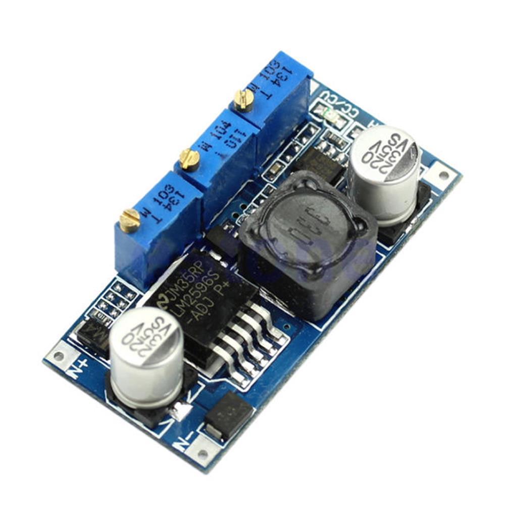
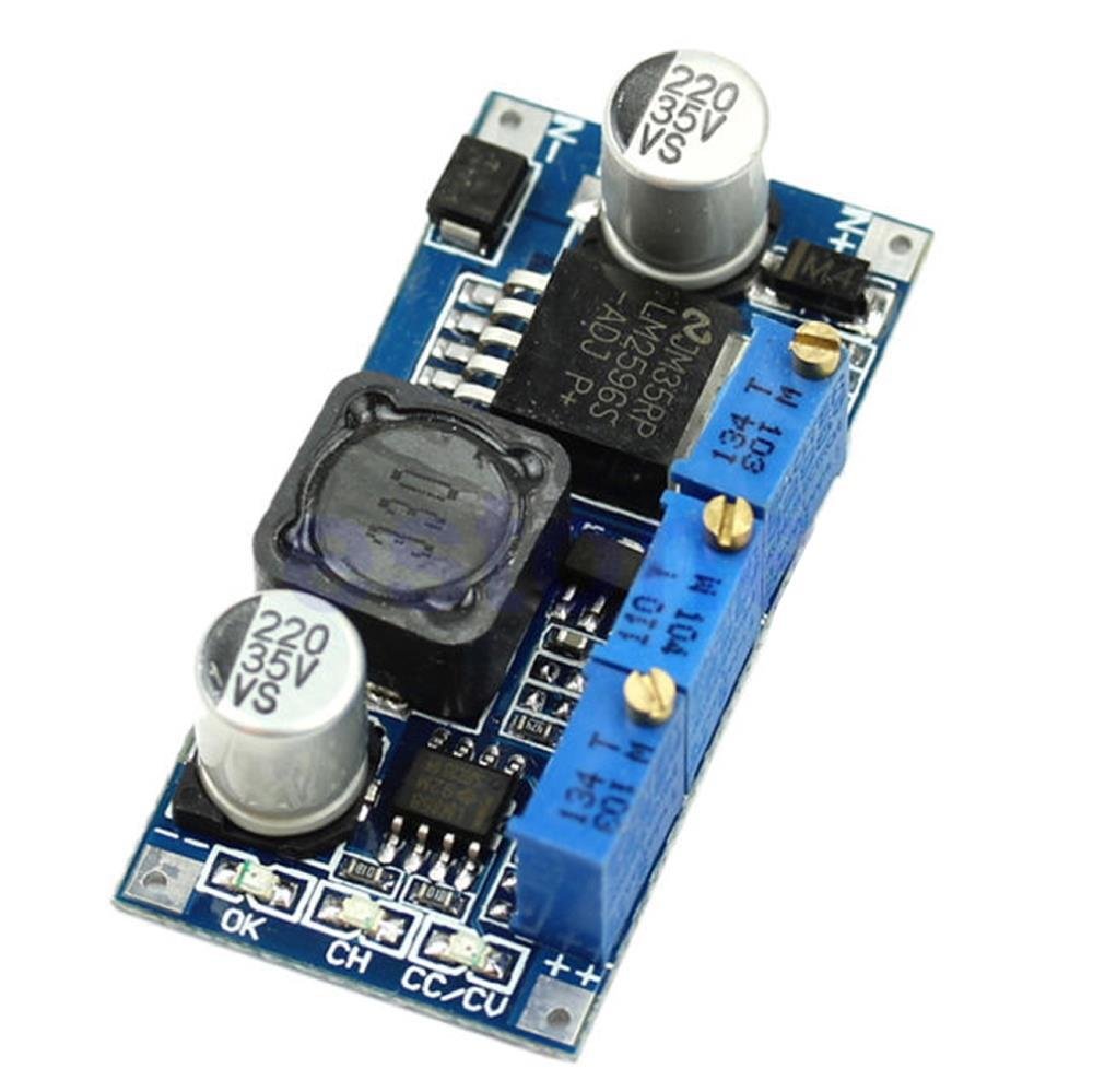
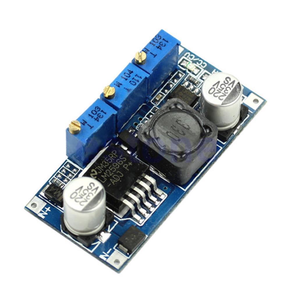
The LM2596 CC/CV Step-Down Buck Converter Module is a compact, adjustable DC-DC power supply that provides both Constant Voltage (CV) and Constant Current (CC) output regulation. It accepts an input voltage from 7V to 35V and delivers an adjustable output from 1.25V to 30V at up to 3A. Two independent potentiometers let you set the maximum output voltage and the maximum output current, while a third potentiometer sets the charge-complete threshold current for battery charging applications.
In CV mode, the module holds the output at a set voltage regardless of load current. In CC mode, the module limits the output current to your set value, allowing the voltage to drop as needed. The module automatically transitions between modes depending on load conditions. Three on-board LED indicators show you which mode is active at a glance — making it especially useful for battery charging, LED driving, and bench testing applications.
⚠️ Important: This module has no input reverse polarity protection. Connecting the input backwards will permanently damage the module. Always double-check polarity before applying power. The output voltage must always be set lower than the input voltage, with a minimum difference of approximately 2V.
⭐ Key Features
- Dual CC/CV Regulation: Independent constant current and constant voltage control with automatic mode switching
- Wide Input Range: Accepts 7V to 35V DC input
- Adjustable Output Voltage: 1.25V to 30V DC via on-board CV potentiometer
- Adjustable Output Current: 0A to 3A via on-board CC potentiometer
- High Efficiency: Up to 92% conversion efficiency (best when output ≈ 80% of input voltage)
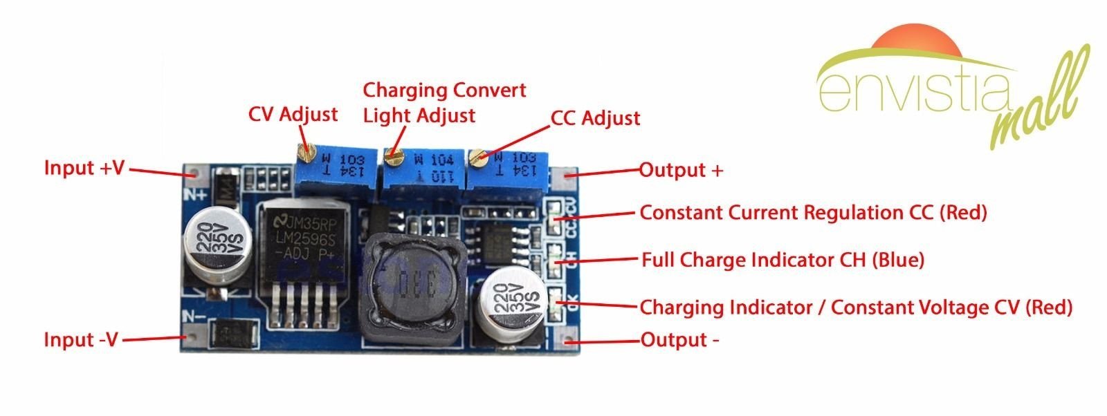
- Three LED Indicators: Red CC/CV (constant current active), Red OK (constant voltage active), Blue CH (fully charged / charge complete)
- Charge-Complete Detection: Adjustable threshold via third potentiometer with blue LED indicator — ideal for battery charging
- Short Circuit Protection: Output is protected via constant current limiting at the CC setting
- Compact Size: Small enough to fit into tight project enclosures
📊 Specifications
| Module Type | DC-DC Step-Down (Buck) Converter with CC/CV |
| Regulator IC | LM2596 |
| Input Voltage | 7V – 35V DC |
| Output Voltage | 1.25V – 30V DC (adjustable via CV potentiometer) |
| Output Current | 0A – 3A (adjustable via CC potentiometer) |
| Output Power | 15W (natural cooling) / 25W (with heatsink) |
| Conversion Efficiency | Up to 92% (higher at higher output voltages; best when output ≈ 80% of input) |
| Min Voltage Differential | ~2V (input must be at least 2V higher than output) |
| Load Regulation | ±1% |
| Voltage Regulation | ±0.5% |
| Dynamic Response | 5% / 200µs |
| No-Load Current | Typical 10mA (12V input to 4.2V output) |
| Full Load Temperature Rise | 45°C |
| Short Circuit Protection | Yes (limits to CC setting) |
| Input Reverse Polarity Protection | No — observe correct polarity |
| Potentiometer Direction | Clockwise = increase, Counterclockwise = decrease |
| Operating Temperature | -40°C to +85°C (derate above 40°C ambient) |
| Connection Mode | Soldered |
| Board Dimensions | Approx. 47 × 23 × 14 mm (1.85 × 0.91 × 0.55 inches) L × W × H (including potentiometers) |
🔧 On-Board Controls and Indicators
Potentiometers
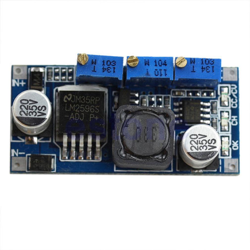
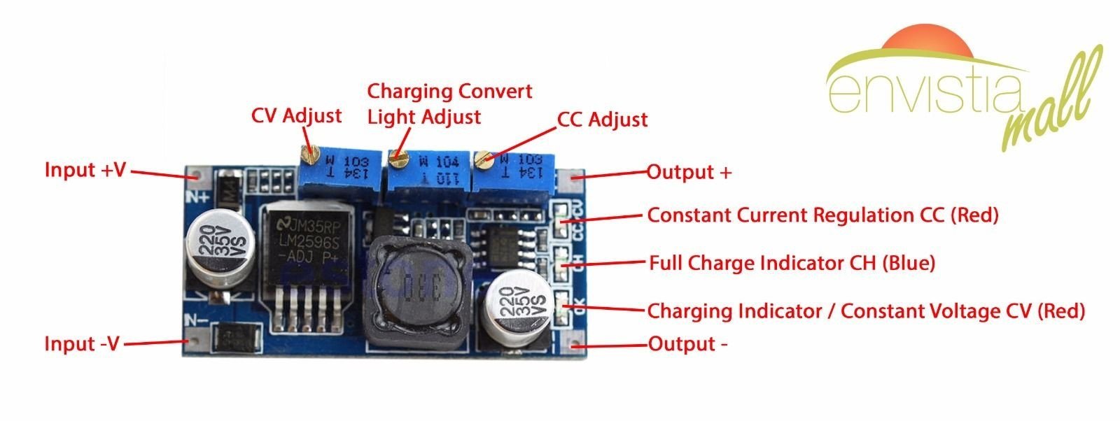
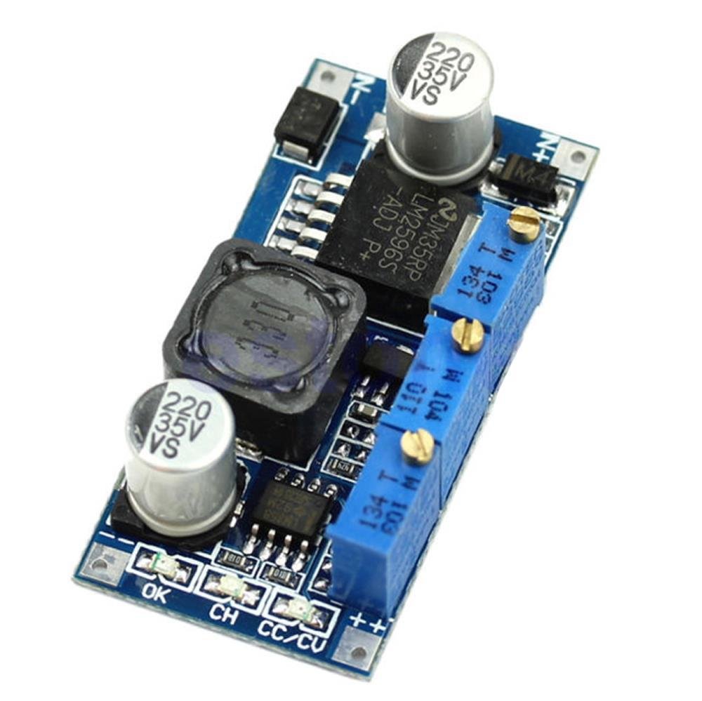
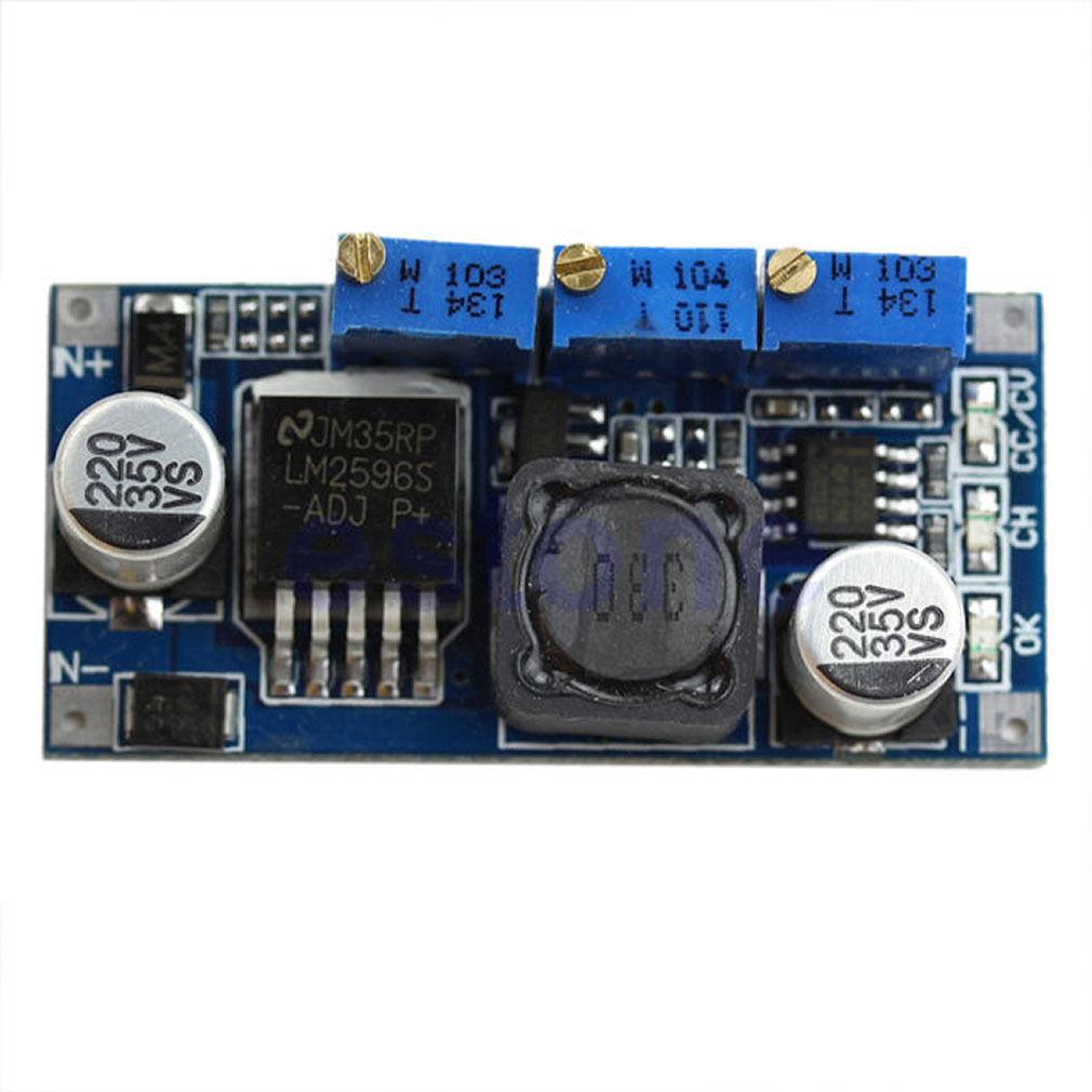
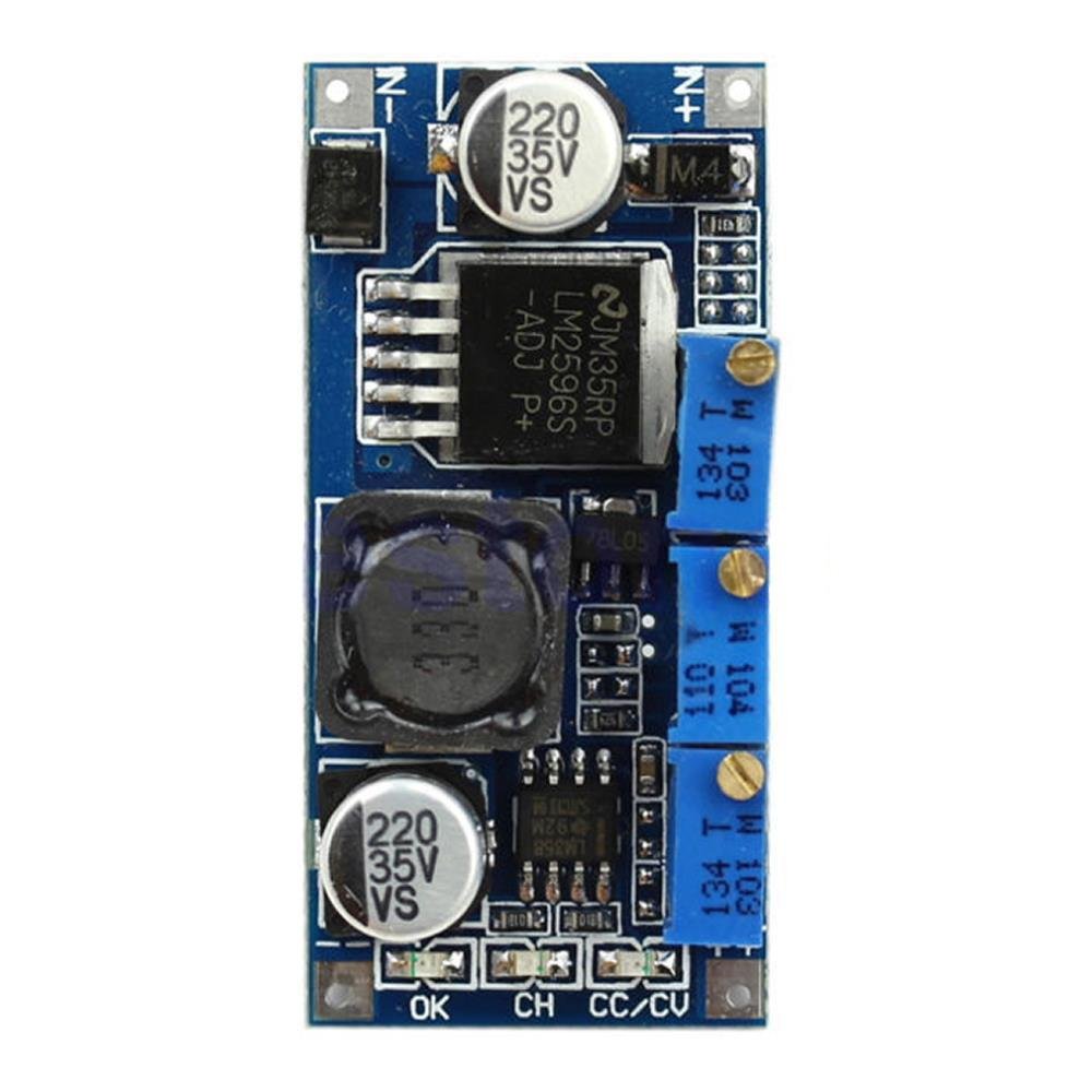
This module has three potentiometers. Each controls a different parameter:
| Potentiometer | Label | Function |
|---|
| 1 | CV | Sets the maximum output voltage (1.25V – 30V) |
| 2 | CC | Sets the maximum output current (0A – 3A) |
| 3 | CH | Sets the charge-complete current threshold (default: 0.1× CC setting) |
LED Indicators
| LED | Color | Label | Meaning |
|---|
| 1 | Red | CC/CV | Constant Current (CC) mode active — load is drawing the maximum set current |
| 2 | Red | OK | Constant Voltage (CV) mode active — output is at set voltage, current is below CC limit |
| 3 | Blue | CH | Charge complete — current has dropped below the CH threshold |
🎯 Typical Applications
- LED and Laser Diode Driver: Constant current driving for consistent brightness and long LED/laser life
- Battery Charging: CC/CV charging profile for lithium-ion, LiPo, LiFePO4, NiMH, NiCd, and lead-acid batteries
- Adjustable Lab/Bench Power Supply: Variable voltage and current-limited output for testing and prototyping
- Solar and Wind Energy: Regulate the output of solar panels or wind turbines to charge energy storage batteries
- Electroplating and Anodizing: Controlled constant current for uniform metal deposition
- Thermoelectric Cooler (Peltier) Control: Precise current control for TEC modules
- Solenoid and Electromagnet Driving: Consistent magnetic field strength via constant current
- LED Dimming: Adjustable current for variable LED brightness
🚀 Getting Started
Before connecting any load, you need to set both the output voltage (CV) and the output current limit (CC). This requires a multimeter.
Step 1: Set the Output Voltage (CV)
- Connect your DC power source (7V–35V) to IN+ and IN−. Double-check polarity.
- Leave the output disconnected (open circuit).
- Power on the input supply.
- Place your multimeter probes on OUT+ and OUT−, set to DC voltage.
- Turn the CV potentiometer until the multimeter reads your desired output voltage.
Step 2: Set the Output Current Limit (CC)
- Switch your multimeter to the 10A DC current range.
- Short-circuit the output — connect your multimeter leads (in current mode) directly between OUT+ and OUT−.
- Turn the CC potentiometer until the multimeter reads your desired maximum current.
- Remove the short circuit.
Step 3: Connect Your Load
Once both CV and CC are set, connect your load (battery, LED, device, etc.) to OUT+ and OUT−. Watch the LED indicators to confirm the module is operating in the expected mode.
⚠️ Important: When measuring short-circuit current, make sure your multimeter is set to the 10A range and the leads are in the correct jacks. Using the wrong range can blow the multimeter's internal fuse.
📦 What's in the Box
- 1 × LM2596 CC/CV DC-DC Step-Down Buck Converter Module
Heatsink, multimeter, wires, screwdriver, and power source are not included. If you plan to operate above 15W output, you will need to supply a heatsink separately.
⚠️ Important Notes
- No input reverse polarity protection. Connecting the input backwards will permanently damage the module. To add protection, place a Schottky diode (such as a 1N5822) in series with the IN+ line.
- Always set and verify CV and CC with a multimeter before connecting your load.
- The input voltage must be at least 2V higher than the desired output voltage for proper regulation.
- Do not exceed 35V on the input.
- For output power above 15W, a heatsink is required on the LM2596 IC. Maximum output with heatsink is 25W.
- If ambient temperature exceeds 40°C, reduce output power or add a heatsink and active cooling.
- This module does not include cell balancing. When charging multi-cell lithium battery packs, always use a BMS (Battery Management System).
- This module does not include a built-in voltage/current display.
- Connections are soldered — this module does not have screw terminals.
- Output short circuit protection is provided via CC mode. A short circuit will continuously draw current at the CC setting — the module does not shut off.
📄 Documentation & Resources
Sold and supported by . Ships from the USA. For wiring diagrams, setup instructions, and troubleshooting, see the User Guide. The manufacturer and Envistia LLC (dba Envistia Mall) are not responsible for any damages or losses resulting from the use of this product. Always follow proper electrical safety practices when working with electronic components. Specifications are based on manufacturer data and are subject to change without notice.