📋 Overview
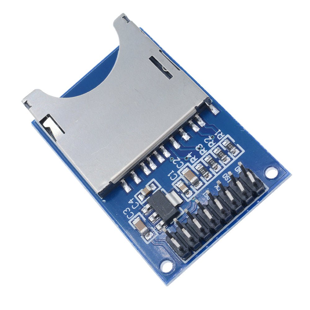
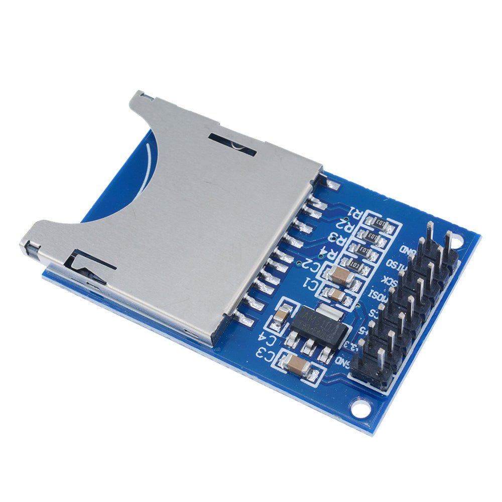
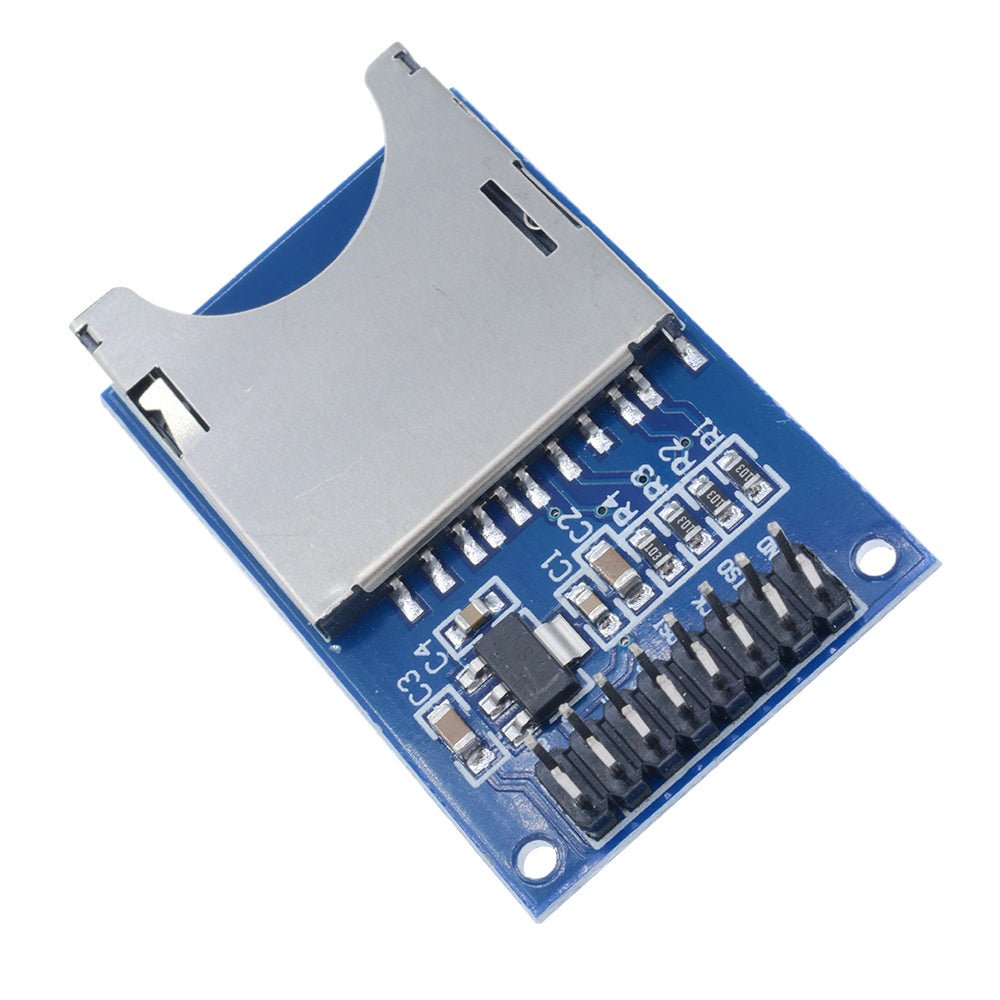
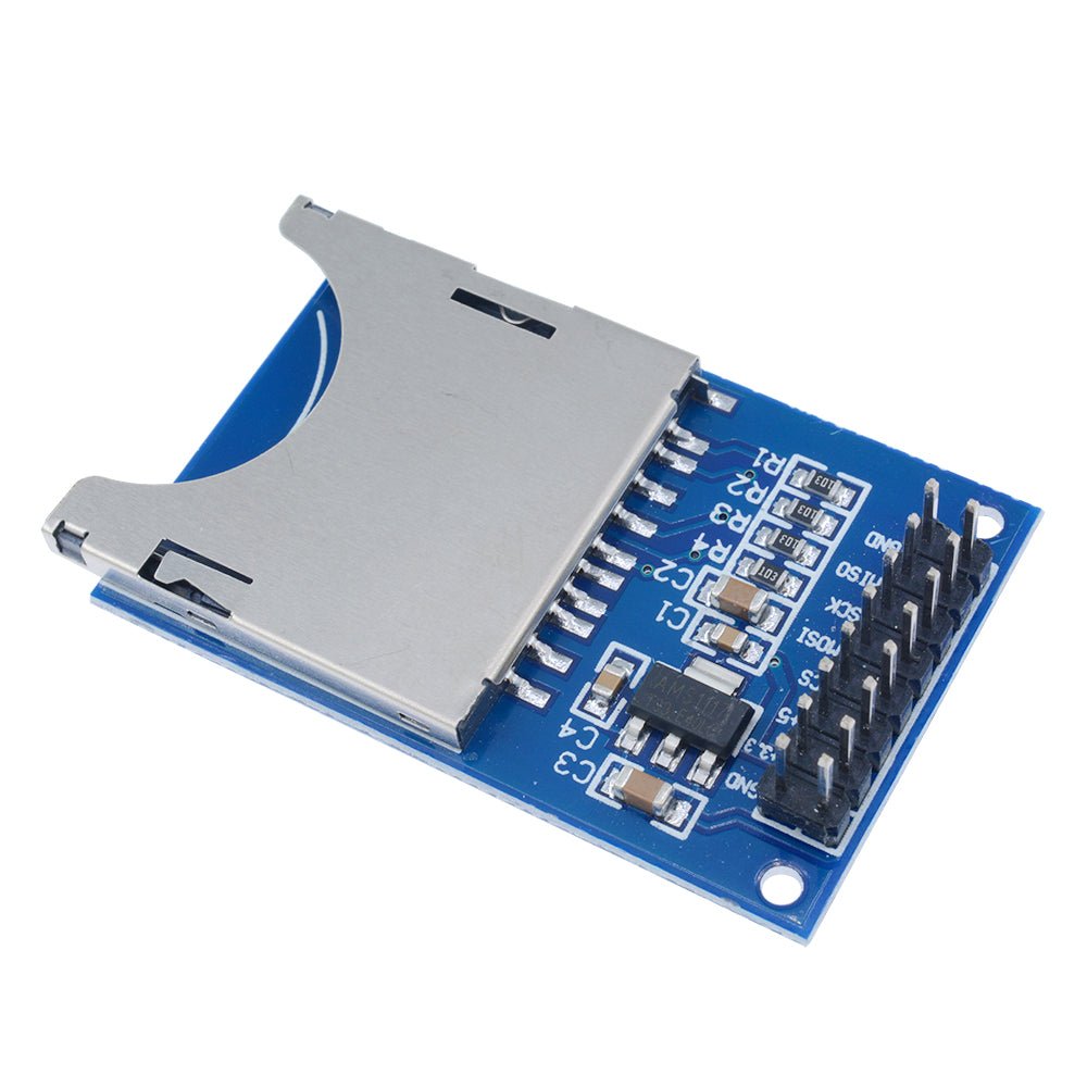
This SD Card SPI Read/Write Module lets you add removable file storage to your Arduino or other microcontroller projects using standard full-sized SD cards. The module communicates over the SPI bus and includes onboard level shifting, making it compatible with both 5V and 3.3V microcontrollers. It works with the built-in Arduino SD library — no extra libraries needed.
Unlike Micro SD modules, this version accepts full-sized SD cards and features separate 3.3V and 5V power input pins, giving you flexibility when working with different microcontroller platforms. Whether you're logging sensor data, storing configuration files, or saving large datasets, this module makes it straightforward.
⚠️ Important: This module has separate 3.3V and 5V power input pins. Connect only one — either 3.3V or 5V — depending on your microcontroller's operating voltage. Connecting both simultaneously may damage the module.
⭐ Key Features
- Full-Sized SD Card Slot — Spring-loaded push-push slot accepts standard SD and SDHC cards (up to 32 GB)
- Dual Voltage Power Input — Separate 3.3V and 5V power pins for flexible microcontroller compatibility
- Onboard Level Shifting — Safely interfaces with both 5V and 3.3V logic microcontrollers
- Standard SPI Interface — Uses MOSI, MISO, SCK, and CS for fast, reliable communication
- Arduino SD Library Compatible — Works with the built-in Arduino SD library right out of the box
- Breadboard Friendly — Header pins on standard 2.54mm pitch plug directly into a breadboard
- LED Indicators — Power LED and activity LED for easy status monitoring
- Write-Protect Support — Full-sized SD cards include a physical write-protect switch
📊 Specifications
| Parameter | Value |
|---|
| Operating Voltage | 3.3V or 5V DC (separate input pins — use only one) |
| Logic Level | 3.3V and 5V compatible (onboard level shifters) |
| Communication Interface | SPI (Serial Peripheral Interface) |
| Supported Card Types | SD (up to 2 GB), SDHC (up to 32 GB) — full-sized cards |
| Supported File Systems | FAT16, FAT32 |
| Card Slot Type | Spring-loaded push-push |
| Header Pins | 9-pin (8 active + 1 NC), 2.54mm pitch |
| Board Dimensions | Approx. 46 × 30 mm (1.81 × 1.18 inches) L × W |
| Indicators | Power LED, Activity LED |
📌 Pin Description
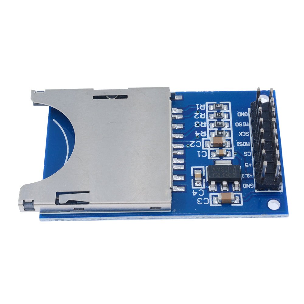
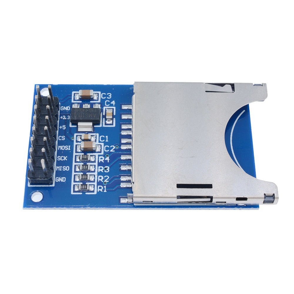
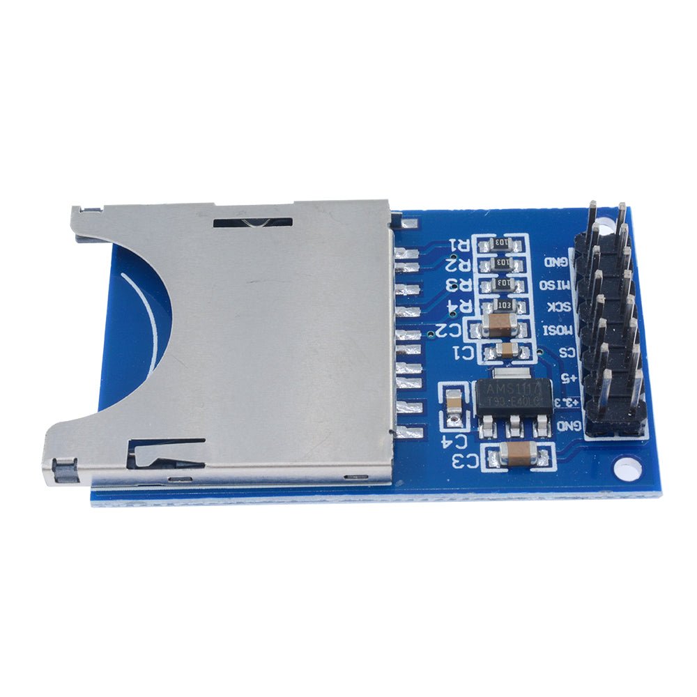
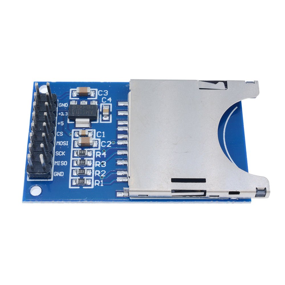
The module has a row of header pins on 2.54mm centers. It can be inserted into a breadboard or connected with female Dupont-style jumper wires.
| Pin | Label | Description |
|---|
| 1 | GND | Ground — must share a common ground with your microcontroller |
| 2 | 3.3V | 3.3V power input — use this pin if your microcontroller operates at 3.3V |
| 3 | 5V | 5V power input — use this pin if your microcontroller operates at 5V |
| 4 | CS | SPI Chip Select — active LOW to select this device on the SPI bus |
| 5 | MOSI | SPI Master Out, Slave In — data from microcontroller to SD card |
| 6 | SCK | SPI Clock — clock signal from microcontroller |
| 7 | MISO | SPI Master In, Slave Out — data from SD card to microcontroller |
| 8 | GND | Ground (duplicate — either GND pin can be used) |
⚠️ Important: Connect only one power pin — either 3.3V or 5V — not both. Connecting both simultaneously may damage the module. If using an Arduino Uno or Nano (5V logic), connect the 5V pin. If using an ESP32 or other 3.3V board, connect the 3.3V pin.
🔌 Wiring to Arduino Uno (5V)
| Module Pin | Arduino Uno Pin |
|---|
| 5V | 5V |
| GND | GND |
| MISO | Pin 12 (MISO) |
| MOSI | Pin 11 (MOSI) |
| SCK | Pin 13 (SCK) |
| CS | Pin 10 (SS) |
Wiring to ESP32 (3.3V)
| Module Pin | ESP32 Pin |
|---|
| 3.3V | 3.3V |
| GND | GND |
| MISO | GPIO 19 (MISO) |
| MOSI | GPIO 23 (MOSI) |
| SCK | GPIO 18 (SCK) |
| CS | GPIO 5 (SS) |
📝 Note: The CS (Chip Select) pin can be connected to any available digital pin, but you must update the pin number in your code to match. Pin 10 is the default used by the Arduino SD library. The MOSI, MISO, and SCK pins are fixed hardware SPI pins and cannot be changed on the Arduino Uno/Nano.
🎯 Typical Applications
- Sensor data logging (temperature, humidity, pressure, GPS coordinates)
- Storing configuration files for microcontroller projects
- Audio WAV file playback
- Image storage for TFT display projects
- GPS track logging
- Flight data recorders for drones and RC aircraft
- Portable measurement and test instruments
- Storing web pages for Arduino-based web servers
📦 What's in the Box
- 1x SD Memory Card Reader/Writer Module with SPI Interface
SD card, jumper wires, and Arduino board are not included.
🛒 What You'll Need
- Arduino Uno, Nano, or compatible board — or any microcontroller with SPI support
- SD or SDHC card — full-sized, 32 GB or smaller, formatted as FAT32
- Jumper wires — female-to-male Dupont wires or a breadboard
- USB cable — to connect your Arduino to your computer for programming
🔌 Compatible With
- Arduino Uno, Nano, Mega, Leonardo, and other Arduino-compatible boards (5V)
- ESP32 and ESP8266 development boards (3.3V)
- STM32 microcontrollers (3.3V)
- Raspberry Pi Pico (3.3V)
- AVR, ARM, and PIC microcontrollers with SPI support
- Any microcontroller with SPI support and 3.3V or 5V logic
⚠️ Important Notes
- Connect only one power pin — either 3.3V or 5V — depending on your microcontroller. Connecting both simultaneously may damage the module.
- Format your SD card as FAT16 or FAT32 before use. exFAT and NTFS are not supported by the Arduino SD library.
- SDXC cards (64 GB and larger) are not supported.
- The Arduino SD library supports filenames in 8.3 format only (e.g.,
DATALOG.CSV). Filenames must be 8 characters or fewer with a 3-character extension. - Always close files after writing with
myFile.close() to prevent data loss. - Do not remove the SD card while the Arduino is actively reading or writing — this can corrupt the file system.
- Full-sized SD cards have a physical write-protect switch on the side. Make sure it is in the unlocked position before attempting to write data.
- For best reliability, use name-brand SD cards (SanDisk, Samsung, Kingston) in the 4 GB – 16 GB range.
📄 Documentation & Resources
Sold and supported by . Ships from the USA. For wiring diagrams, sample code, and troubleshooting, see the User Guide linked above. The manufacturer and Envistia LLC (dba Envistia Mall) are not responsible for any damages or losses resulting from the use of this product. Always follow proper electrical safety practices when working with electronic components. Specifications are based on manufacturer data and are subject to change without notice.