
2519 S Shields Street
Suite 1K #665
Fort Collins, Colorado, 80526 US
+1 970-372-2401
support@envistia.com
Free worldwide shipping
Free returns
Carbon neutral
Secure payments
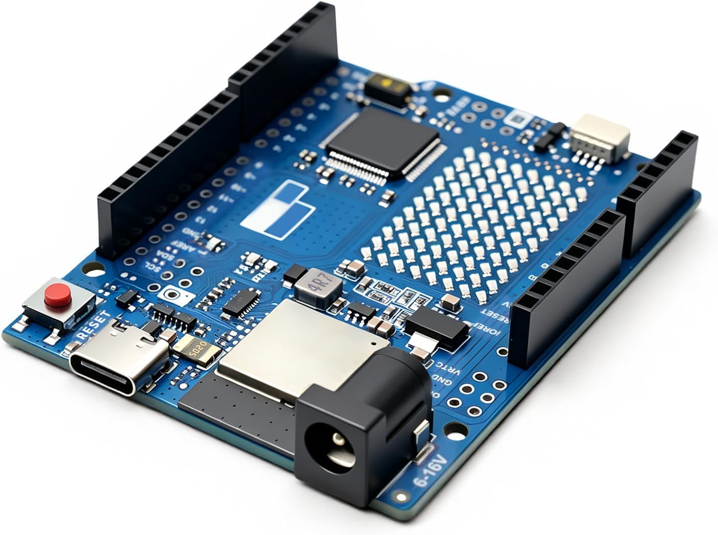
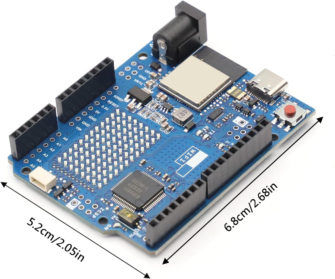
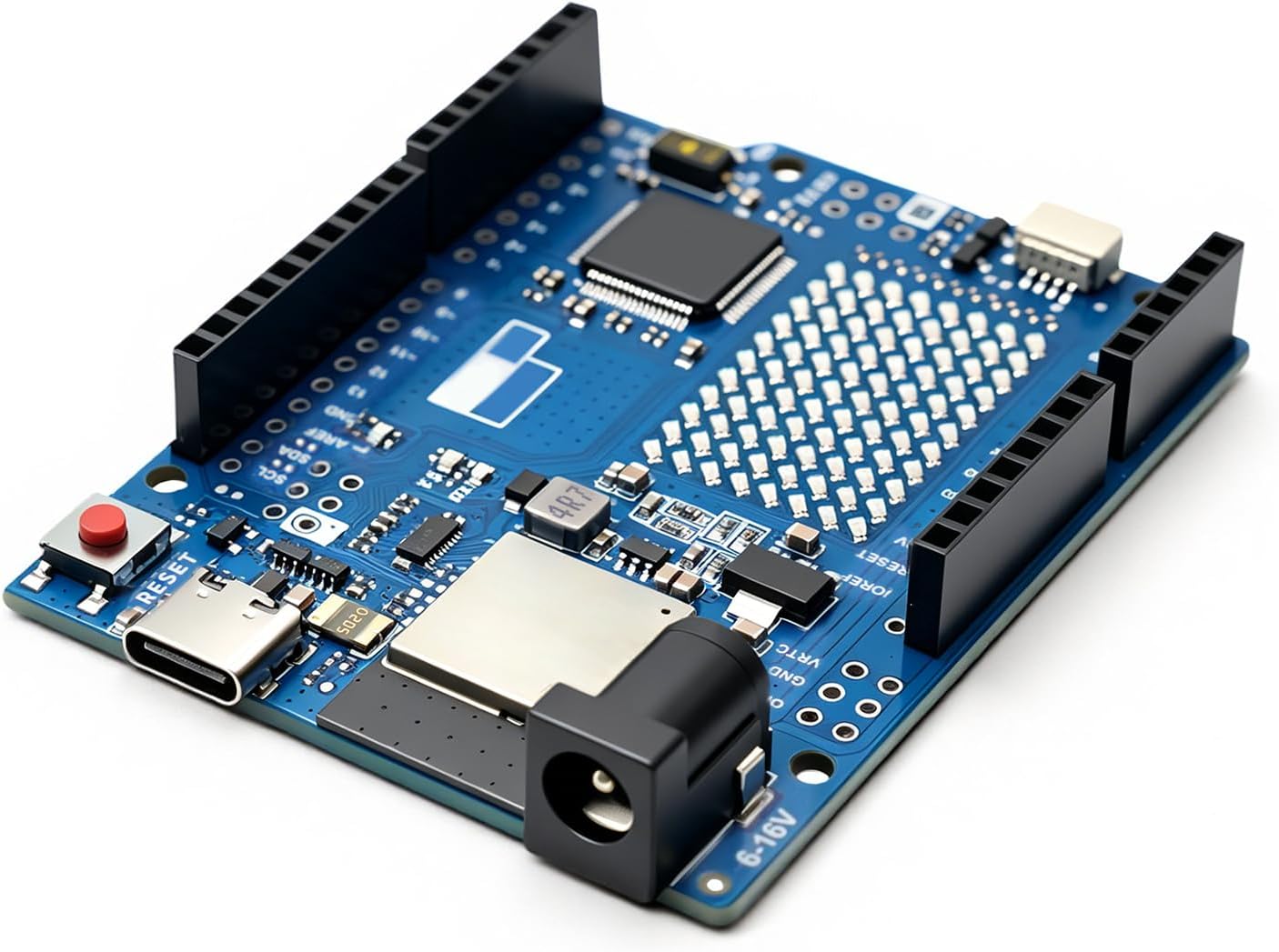
The UNO R4-Compatible WiFi Board is a UNO-format development board built around the same core chipset found in certain officially branded UNO R4 WiFi boards: a 32-bit Renesas RA4M1 microcontroller paired with an ESP32-S3 module for Wi-Fi and Bluetooth. This is a compatible board, not a genuine Arduino-branded product — but because it uses the identical RA4M1 and ESP32-S3 chipset, it runs the same sketches, libraries, and board packages used across the maker community.
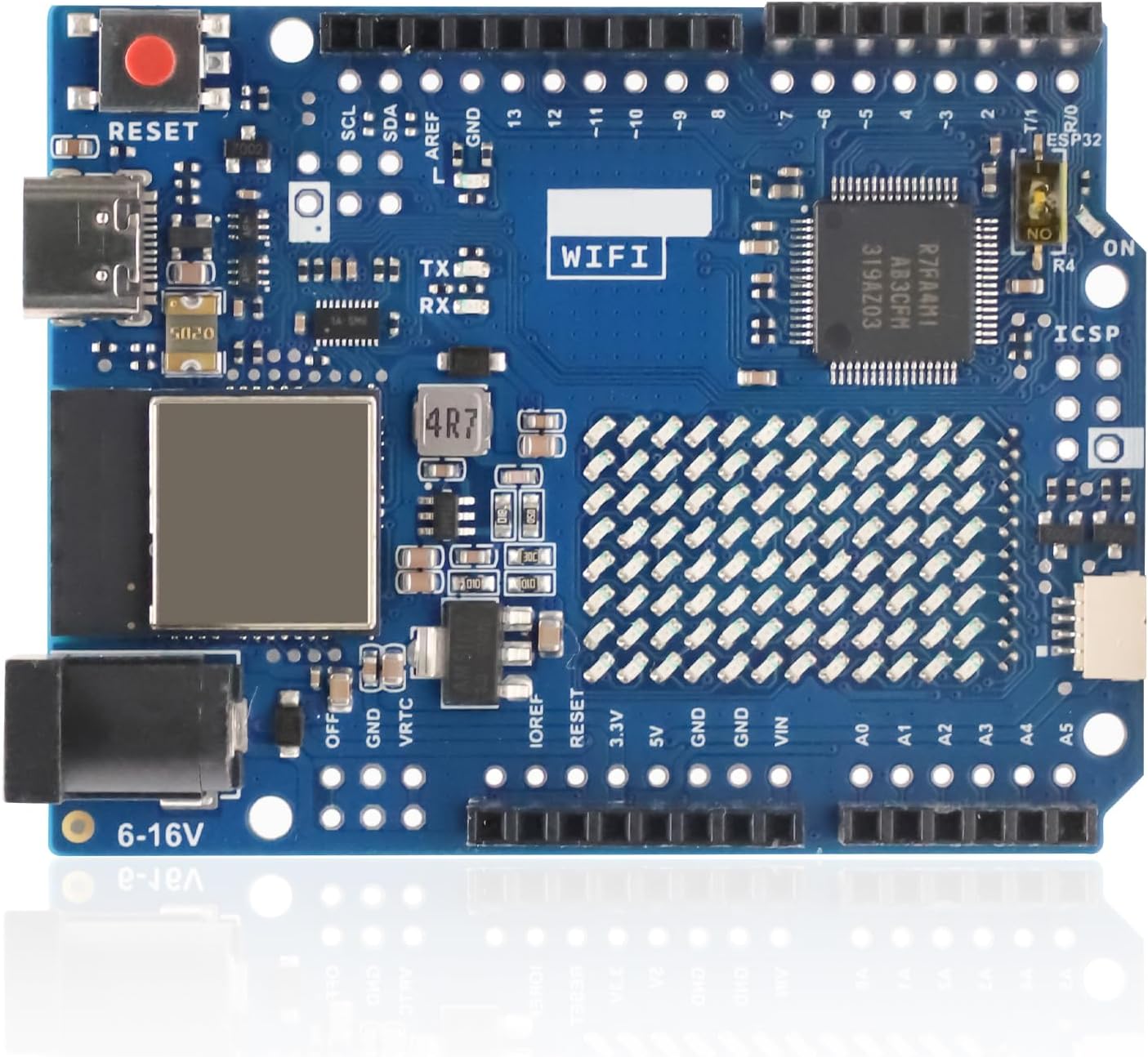
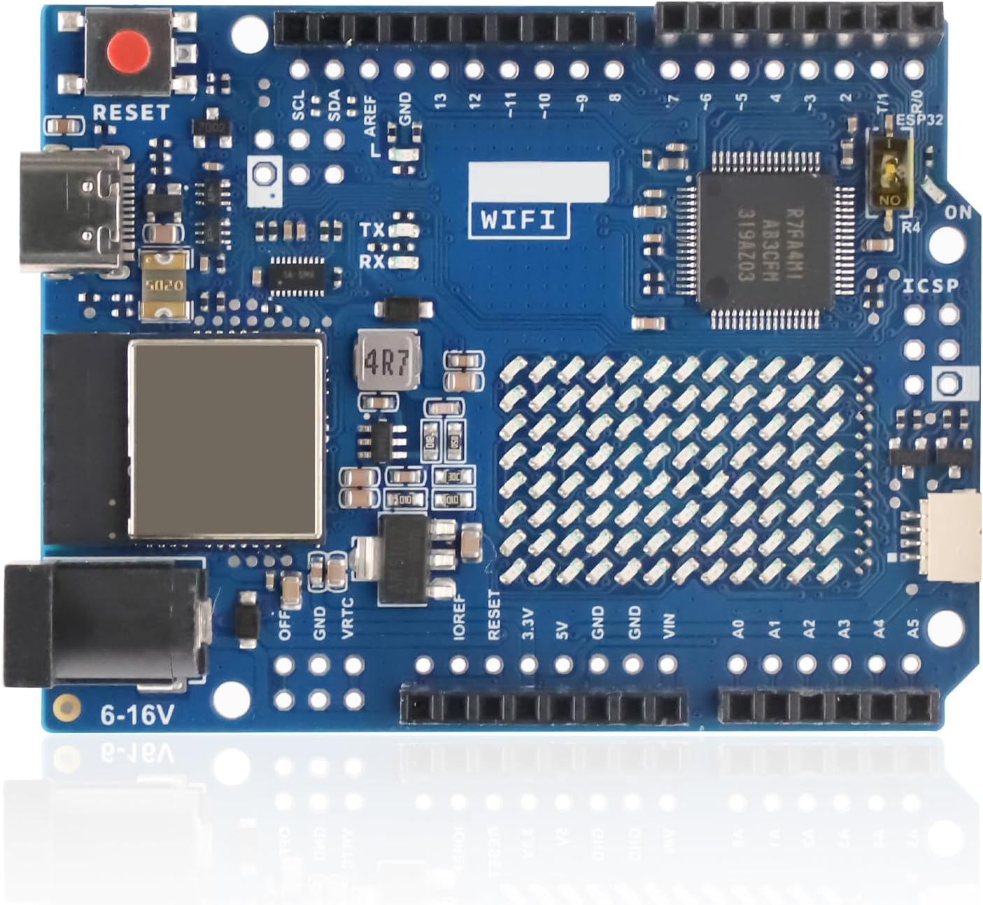
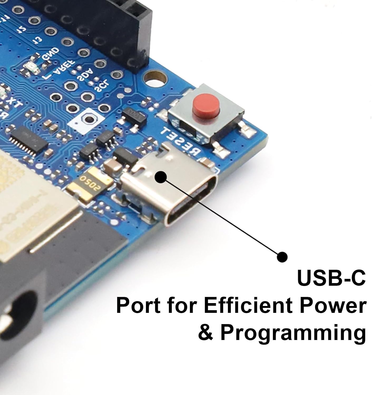
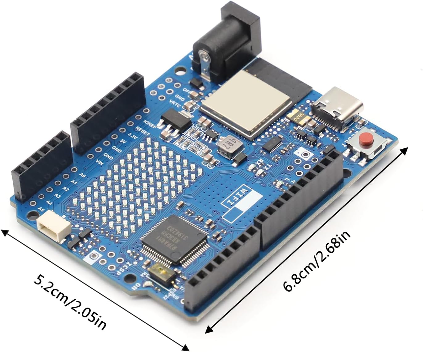
Under the hood, this board uses a dual-MCU design: the RA4M1 runs your sketch and controls all onboard peripherals, while a separate dual-core ESP32-S3 coprocessor handles Wi-Fi and Bluetooth 5 wireless connectivity. On top of that, you get a built-in 12x8 LED matrix, a 12-bit DAC, an onboard op-amp, USB-C, a Qwiic I2C connector, and CAN bus support — all while keeping the classic 5V UNO operating voltage and pin layout for shield compatibility.
Looking at the board from the top, with the USB-C port and DC jack at the top-left and the digital header along the top edge:
| Pin | Label | Function |
|---|---|---|
| D0 / D1 | RX / TX | UART Serial Receive / Transmit |
| D2, D3 | Digital / Interrupt | GPIO with external interrupt support |
| D3, D5, D6, D9 | PWM (~) | PWM-capable digital pins |
| D4 | Digital | General purpose GPIO |
| D10 | CANTX0 | CAN Bus Transmit (requires external transceiver) |
| D11–D13 | SPI / SCK | SPI Controller Out/In, Clock (D13 doubles as CANRX0) |
| D13 | CANRX0 | CAN Bus Receive (requires external transceiver) |
| SDA / SCL | Digital header I2C | Standard I2C bus (also on A4/A5) |
| A0 | Analog In / DAC | Analog input 0 or 12-bit DAC output |
| A1 / A2 / A3 | OPAMP+ / OPAMP− / OPAMP Out | Onboard operational amplifier connections |
| A4 / A5 | SDA / SCL | Standard I2C bus (shared with digital header) |
| Qwiic Connector | SCL / SDA / 3V3 / GND | Secondary I2C bus, 3.3V only |
| VIN | Power In | 6–24V input (barrel jack or header) |
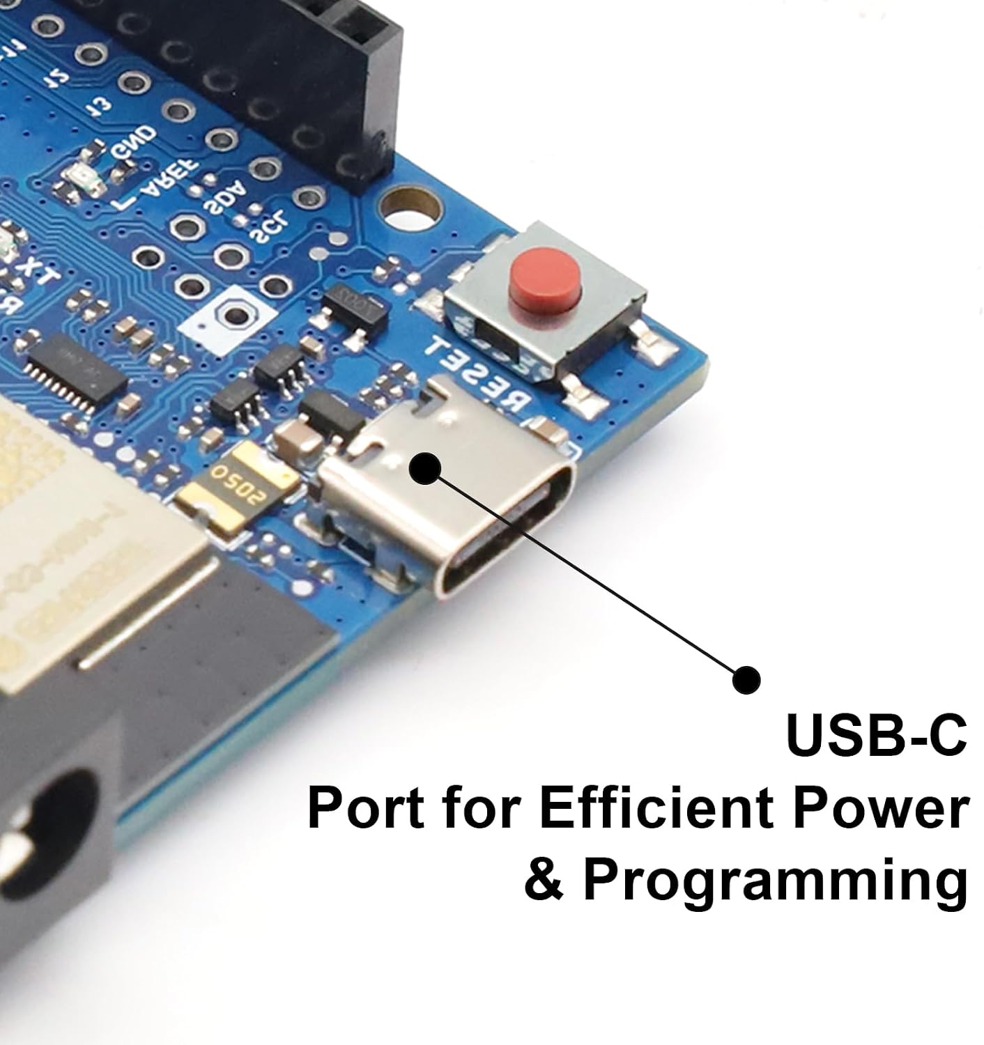
| USB-C | Power / Data | 5V power, programming, and serial communication |
| +5V / +3V3 | Power Out | Regulated power rails for external components |
⚠️ Important: The ESP32-S3 coprocessor, its dedicated header, and the Qwiic connector operate at 3.3V and are not 5V tolerant. Never connect a 5V signal to these — doing so can permanently damage the ESP32-S3 module.

| Main Microcontroller | Renesas RA4M1 (R7FA4M1AB3CFM), 48 MHz Arm Cortex-M4 with FPU |
| Wireless Module | ESP32-S3-MINI-1-N8, dual-core Xtensa LX7, Wi-Fi 4 (2.4 GHz) & Bluetooth 5 LE |
| Flash / SRAM / EEPROM | 256 kB / 32 kB / 8 kB |
| Operating Voltage | 5V (RA4M1) / 3.3V (ESP32-S3, internal only) |
| Input Voltage (VIN) | 6–24V (barrel jack or header) |
| USB Input Voltage | 4.8–5.5V via USB-C (do not exceed 5V) |
| Digital I/O Pins | 14, each rated up to 8 mA max |
| Analog Input Pins | 6 (A0–A5) |
| DAC Resolution | Up to 12-bit (on pin A0) |
| LED Matrix | 12x8 (96 LEDs), red, charlieplexed |
| Communication | 1x UART, 1x SPI, 2x I2C (incl. Qwiic), 1x CAN (external transceiver required) |
| USB Connector | USB-C |
| Operating Temperature | -40°C to +85°C |
| Board Dimensions | Approx. 68.6 × 53.3 × 15 mm (2.70 x 2.10 x 0.59 inches) L × W × H |
The RA4M1's CAN controller is built into the microcontroller but has no onboard transceiver. You'll need an external CAN transceiver module (such as an SN65HVD230) to connect to an actual CAN bus network.
| Board Pin | CAN Transceiver Pin |
|---|---|
| D13 (CANRX0) | CAN RX |
| D10 (CANTX0) | CAN TX |
| 3.3V | VIN |
| GND | GND |
📝 Note: A CAN transceiver is required for this board to communicate on a real CAN bus network — the pins alone will not work without one.
USB-C cable, jumper wires, and shields are not included.
Sold and supported by Envistia Mall. Shipped from the United States. This product is a compatible board using the same RA4M1 and ESP32-S3 chipset as certain officially branded microcontroller boards, but it is not manufactured, endorsed, or affiliated with the original brand owner, and is not sold under that brand's trademark. Please refer to the linked User Guide for full setup instructions, pinout details, and safety information. Envistia Mall is not liable for damage resulting from improper wiring, incorrect voltage, or misuse of this product. Always follow proper electrical safety practices when working with development boards and connected components.

loading